Introduction
We've all been there, fellow engineers, staring down the barrel of a differential relay test and wondering... just what current do I inject to hit that elusive slope point, or distinguish stable from unstable conditions? It's a common struggle, and one that often leads us to rely on the tried-and-true method of referencing previous test reports. But what if we could break free from the shackles of old data and master the art of calculating these critical values ourselves?
That's the journey we're embarking on today, folks. We'll ditch the copy-paste approach and dive deep into the calculations behind plotting the differential relay curve and finding those crucial secondary currents. No more relying on black boxes or blind trust in past reports.
By the end of this blog, you'll be confidently injecting the right currents, identifying stable and unstable conditions, and plotting beautiful differential relay curves.
So, are you ready to transform from a data copy-paster to a curve-plotting, current-injecting maestro? Let's begin!
Stay tuned for the next part of this blog, where we'll crack open the formula vault and dive into the heart of the calculations!
Table of Contents
Differential Characteristics
 |
| Fig 1 : Differential Characteristic |
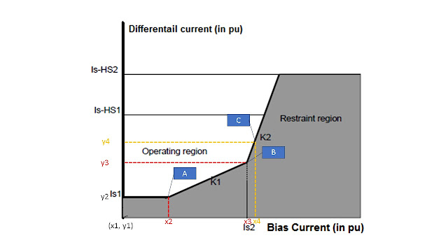
The curve above represents Differential relay characteristics plotted between Differential current (Idiff on Y Axis) and Restraining or Bias current (Ires on X axis). The shaded area of the curve is non-operating region. Any fault that falls in unshaded region will trip the breakers. Following equation gives us idea about the region separation.
 |
| Fig 2 : Differential Equations |
Let's understand this in simple language. I1 is primary current entering the equipment and I2 is current leaving the equipment. In case there is fault inside the equipment, this will no longer be true. Let, fault takes place after the equipment, both currents will rise proportionately and thus balance will be maintain of the currents. Following animation explains this same concept.
Isn't it easy to understand??? Sure. So, let's touch tricky part now.
Above concept can be used in case of Motor and Generator stator winding differential protection since there is no magnitude difference & phase shift between current entering and leaving the machine. CT ratio's are same at both side and so the secondary currents.
 |
| Fig 3 : Differential Scheme Connections |
In case of transformers, magnitude difference & phase shifts are introduced. Also, inrush current plays vital role in the scheme.
Realising Differential Characteristic
Let's start plotting out differential curve as applied to Micom P64x relay. Transformers specifications are considered as below.
Relay settings for Micom P643 are as follows :
Locating different Points on Curve
As referred to Fig 1 : Differential Characteristic and Fig 5 : Micom P643 Relay Differential Settings, We have values of Is1, Is2, Ihs1, Ihs2. We also know slope values for curve lines.
Point A
We have to extend Line AB towards origin. Coordinates of A is (x2, y2). Slope of line in known i.e. 30%, y2 = 0.2pu, we can find x2 as
Point B
We have coordinates of A as (x2 = 0.67, y2 = 0.2) and of B as (x3 = 3, y3 = ?).
As we know, slope of a line is given by
Solving for y3, we get
We can assume some point on x axis after x3. Lets take is as
x4 => x3 + 0.5 = 3.5pu.
Now, y4 can be found out as
y4 = y3 + [k2 * (x4 - x3)] = 0.899 + (0.7*0.5) = 1.25pu
or
y4 coordinates are (x4=3.5, y4=1.25).
We have points as follows:
- A => (x2=0.67, y2=0.2)
- B => (x3=3, y3=0.899)
- C => (x4=3.5, y4=1.25)
Similarly, we can find out various points on the characteristics.
Calculating Current based on points
Let's proceed finding out currents to achieve these differential and restraining currents, in terms of CT primary and secondary currents.
Since, transformer primary and secondary side CT ratios are different, we have to calculate matching factor (MF).
MF is calculated for Primary and secondary winding separately. For HV side, CT ratio of HV is divided by Rated current of HV to get MF(hv).
CT Secondary current at 100% loading is given byI1 - I2 = 0.2
I1 + I2 = 0.67 * 2
Solving gives us I1 = 0.77pu & I2 = 0.57pu
To find out CT secondary currents of HV and LV side, we have to multiply above currents by respective matching factors.
i1 = I1 * MF(hv) = 0.77 * 1.1431 = 0.8802A
i2 = I2 * MF(lv) = 0.56 * 1.1951 = 0.6693A
I1 - I2 = 0.899
I1 + I2 = 3 * 2
This gives us, I1 = 3.4495pu and I2 = 2.5505pu
i1 = I1 * MF(hv) = 3.4495 * 1.1431 = 3.9431A
i2 = I2 * MF(lv) =2.5505 * 1.1951 = 3.0481A
Currents at Point C are as follows :
I1 - I2 = 1.25
I1 + I2 = 3.5 * 2
This gives us, I1 = 4.1250pu and I2 = 2.8750pu
i1 = I1 * MF(hv) = 4.1250 * 1.1431 = 4.7153A
i2 = I2 * MF(lv) =2.8750 * 1.1951 = 3.4356A
Conclusion
Hope, this blog will help you understand and test your next differential relay. See your in Part-2 in which we'll discuss actual relay testing procedure for Differential protection.
P.S. Don't forget to share your own differential relay testing experiences and struggles in the comments below.


Can you spot a mistake in the blog???
ReplyDeleteHello Brother, When you will post a part-2
ReplyDelete