Introduction
Table of Contents
AVR
AVR plays an important role in controlling the voltage output of a synchronous generator. For a synchronous generator, an AVR is a control system that monitors the output voltage of the generator and adjusts the excitation of the field to maintain a stable and preset voltage level
Here's how it works: As the load on the generator changes, the voltage output can change. The AVR senses this change and adjusts the amount of current supplied to the generator field windings. By controlling the field excitation, the AVR ensures that the generator produces a stable and consistent output voltage even under varying load conditions In summary, the AVR of synchronous generators helps maintain stability by ensuring field interest, stability of power supply It also ensures reliability.
Part of AVR
Dummy Load
A dummy load test is process in which a device, commonly known as a dummy load, is used to simulate the electrical load that real equipment will put in. This is usually done to test or demonstrate the performance of power sources such as amplifiers, power supplies, etc. operate without necessarily connecting them to actual loads It absorbs the power generated by the devices under test, enabling inspection and analysis without the need for an active external system
Requirement of Dummy load test
A dummy load test of an automatic voltage regulator (AVR) is conducted to verify that the AVR system operates properly under controlled conditions and to ensure that it operates properly under controlled conditions Some reasons for dummies load testing for AVR is:
1. Functional validation: The dummy load test allows functional validation of the AVR. Tests that simulate load conditions ensure that the AVR responds appropriately to changes in the generator, and maintains the voltage within acceptable limits
2. Stability testing: This helps to evaluate the stability of the AVR system. To check how well the AVR maintains a stable output voltage, the generator is subjected to various load conditions. This is important for the reliable operation of the power generation system.
3. Performance evaluation: Testing provides a means to evaluate the performance of an AVR in a real-world environment. It allows engineers to monitor how the AVR handles load fluctuations and adjust field excitement to maintain desired power levels.
4. Troubleshooting: If there is a problem with the AVR or generator voltage regulation, a dummy load test can help detect and diagnose problems. It provides a controlled environment to monitor AVR behavior and pinpoint any errors or deviations from expected performance.
5. Commissioning and Maintenance: Dummy load testing is usually part of the commissioning process for new AVR systems. In addition, the routine maintenance program can include dummy load tests to identify any degradation in AVR performance to ensure continued reliability In summary, dummy load testing for AVR is a practice active verification of its performance, checking stability, troubleshooting and ensuring proper operation of the synchronous generator
List of required tool and tackles
Certainly, here is a technical list of
testing/measuring instruments required for AVR dummy load testing:
1. Dummy Load: Halogen lamp or incandescent lamp load
rated at 500W or 1000W, providing a controllable and reproducible electrical
load.
2. DC Ammeter: Instrument for measuring direct
current (DC) in amperes, used to quantify and monitor the current flowing
through the dummy load.
3. DC Voltmeters: Instruments for measuring direct
current (DC) voltage, employed to gauge and monitor the AVR output
voltage.
4. Wire Loops: Several wire loops for making
electrical connections, facilitating the setup and interconnection of
components during the dummy load test.
5. Schematic Drawing: A detailed schematic drawing
illustrating the electrical connections and configurations of the AVR system, dummy load, and associated instrumentation.
6. Previous Test Report (if available): Any existing test reports from previous assessments, serving as a reference to compare and analyze historical data regarding the AVR system's performance.
These instruments collectively enable a comprehensive dummy load test, providing insights into the Automatic Voltage Regulator's functionality, stability, and overall performance under different load scenarios.
Following procedure is applicable to BHEL make DAVR's and may vary for different OEM AVR's.
Procedure
1. Switch AVR to local mode from HMI
2. Switch off Q3 isolator to isolate AVR output to
Main exciter and put AVR in test mode
3. Disconnect output cable to main exciter field winding and insulate. Connect dummy load at these terminals.
5. Connect DC voltmeter (0-500V Range) and DC ammeter
(0-10A range) in the dummy load circuit.
6. Change active channel from Channel 1 to Channel 2. Switch off Channel 1 power supply and put it in internal control mode by switching on S865 dip switch 1.
7. Switch on channel 1 power supply. Set channel 1 as
active channel in manual mode and switch off Channel 2 power supply.
8. Simulate Digital Input for speed >90% by looping at appropriate terminals.
9. Connect multimeter to Uc of channel 1 at UN0663 card with respect to 0V terminal.
10. Switch on Field breaker and excitation from HMI.
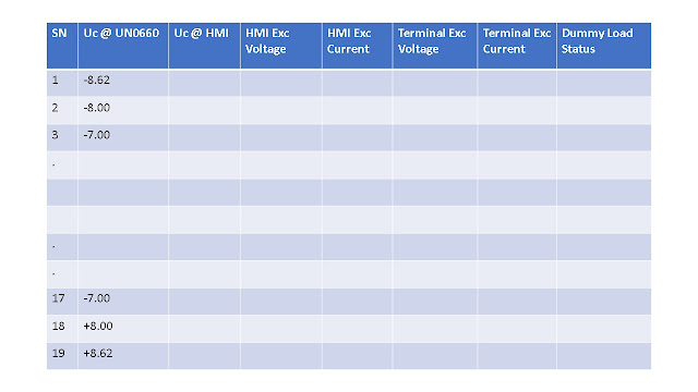
11. Note down reading at minimum Uc value of channel 1 at
HMI (generally in the range of -8.55 to -8.65V DC appx) at UN0663, AVR output voltage and current (at HMI, terminals and Analog
meters), rotor current as per Table 1.
 |
| Table 1 : Dummy Load Parameter Measurement |
12. Now slowly increase AVR output by pressing raise
button on UN0663.
13. Note down readings at various values of Uc till
Ucmax ( generally in the range of +8.55 to +8.65V DC appx).
14. Keep monitoring lamp status during whole phase.
15. Note down diode protection fuse voltage drop (Table 2), and
various channel parameters (Table 3) at Ucmax.
16. Now, slowly decrease Uc till Ucmin and switch off excitation and field breaker.
17. Repeat above steps for channel 2.
18. Same test can be repeated with individual bridge
in circuit.
19. Compare test result with previous or
commissioning test results.
20. Restore all bypass / isolations / forced logic to normal.


